
1. Introduction to Coverage Concepts in NTN
In terrestrial networks, the concept of coverage is straightforward, a cell defines both the radio coverage and the logical identity. In NTN, this relationship is no longer direct.
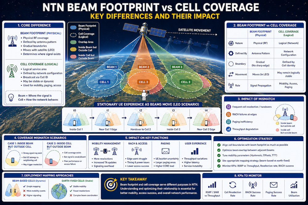
- Beam footprint defines physical coverage
- Cell coverage defines logical network representation
- These two may overlap but are not always identical
Understanding this distinction is critical for planning, optimization, and troubleshooting.
2. What is Beam Footprint in NTN
Beam footprint refers to the physical area on earth illuminated by a satellite beam.
- Determined by satellite antenna design
- Can be wide (GEO) or narrow (LEO spot beams)
- Moves in LEO systems
Key characteristics:
- Purely RF/physical concept
- Defined by power distribution and antenna pattern
- Has gradual boundaries (no sharp edges)
3. What is Cell Coverage in NTN
Cell coverage represents the logical service area associated with a Cell ID.
- Broadcast to UE via system information
- Used for:
- Cell selection
- Mobility
- Paging
Important:
- Cell coverage may be mapped to one or more beams
- Logical boundaries may not perfectly match RF coverage
4. Beam Footprint vs Cell Coverage (Core Difference)
| Aspect | Beam Footprint | Cell Coverage |
|---|---|---|
| Nature | Physical (RF) | Logical (Network) |
| Defined By | Antenna pattern | Network configuration |
| Boundary | Gradual | Defined by cell identity |
| Movement | Moves (LEO) | May remain logically stable |
| Role | Signal propagation | Mobility & signaling |
5. Why This Difference Matters in NTN
In NTN:
- A UE may still be inside beam footprint but lose cell coverage
- Or remain in same cell while beam changes
Impact areas:
- Mobility behavior
- RACH success
- Paging efficiency
6. Beam Movement vs Cell Stability (LEO Case)
In LEO systems:
- Beam footprint continuously moves
- Cell identity may:
- Move with beam
- Or remain logically anchored
Two models:
- Beam based cells (dynamic cell movement)
- Earth fixed cells (beam remapping to fixed cells)

7. Coverage Mismatch Scenarios
Common field situations:
Case 1: UE inside beam but poor performance
- Cause:
- Cell edge condition
- Low SINR despite coverage
Case 2: UE exits cell but still receives signal
- Cause:
- Logical boundary crossed
- Result:
- Reselection or handover triggered
8. Impact on Mobility Management
Beam vs cell mismatch affects:
- Cell reselection frequency
- Handover decisions
- Tracking Area updates
Key issue:
- Excessive mobility signaling if mapping is not optimized
9. Impact on RACH and Access Performance
RACH depends on both:
- Signal strength (beam footprint)
- Correct cell configuration
Problems occur when:
- UE selects cell at beam edge
- Timing and power conditions are not ideal
10. Troubleshooting Scenarios
Common symptoms:
- Good RSRP but low throughput
- Frequent cell reselection
- High RACH failure at edges
Root causes:
- Beam - cell misalignment
- Poor mapping strategy
- Coverage imbalance across beams
11. Optimization Strategy from RF Perspective
Key actions:
- Align cell boundaries with beam footprint as much as possible
- Optimize beam overlap regions
- Tune mobility parameters:
- Hysteresis
- Offsets
Monitor:
- RSRP vs throughput correlation
- Cell reselection rate
- Beam level performance KPIs
12. Practical Deployment Approaches
Operators typically:
- Use beam based cells for simplicity
- Or use earth fixed cells for mobility stability
Trade off:
- Beam based:
- Simpler mapping
- Higher mobility events
- Earth fixed:
- Stable mobility
- Complex beam coordination
13. Key Takeaways
- Beam footprint is physical, cell coverage is logical
- They do not always match in NTN
- Misalignment leads to mobility and performance issues
- Optimization requires balancing RF coverage and logical design